Chapter Three: MIDI
8. MIDI Data Format: SysEx Extensions
Two manufacturer IDs, 7F and 7E, are reserved for universal System Exclusive messages, which any maker's equipment can respond to: 7F for real time messages, which act at once, and 7E for non-real time ones such as sample transfers. The most important of them follow.
MIDI Time Code (MTC)
As mentioned in the previous section, MIDI clock, part of the system real time code class, is a relative timing device, since it depends on musical time or tempo. A real need developed to synchronize MIDI with film, audio devices, video devices, etc. This required absolute timing. The film and television industries already had their own time code, called SMPTE time code after the Society of Motion Picture and Television Engineers, which standardized it. In 1987, four years after MIDI 1.0 was adopted, a new class of code called MIDI Time Code was added to act as a bridge between MIDI and SMPTE. External devices would convert MIDI Time Code to SMPTE and vice versa. Sequencers could be synchronized to video decks for film scoring. Time code read from the videotape, either linear time code (LTC) recorded on an audio track or vertical interval time code (VITC) hidden in the picture, was converted to MIDI Time Code, often by a MIDI interface such as MOTU's MIDI Timepiece, and the MTC then locked the sequence to the tape. This is still in play today, with DAWs such as Pro Tools sync'ing up on mixing stages with digital video, using MTC and SMPTE.
MIDI Time Code uses two kinds of message: short quarter-frame messages, which are System Common messages, while the music runs, and a longer full message, which is universal real time system exclusive, when it jumps to a new place. Both carry the same running time as SMPTE time code in hours:minutes:seconds:frames. However, unlike SMPTE, MTC also uses a 2-bit field to indicate the intended frame rate, as shown in the table below (rr). The complete time takes 4 data bytes (32 bits), though only 24 bits are used; the rest are 0s, the first in each byte because every MIDI data byte must begin with 0. The following table shows how the time is laid out in those bytes.
| Data Byte 1 | Data Byte 2 | Data Byte 3 | Data Byte 4 |
|---|---|---|---|
| 0rrhhhhh | 00mmmmmm | 00ssssss | 000fffff |
| r=frame rate code (0–3)* h=hour (0–23) |
m=minute (0–59) | s=second (0–59) | f=frame (0–29, or less depending on fps) |
*Frame rate bits (rr): 00=24 fps, 01=25 fps, 10=29.97 fps drop-frame, 11=30 fps
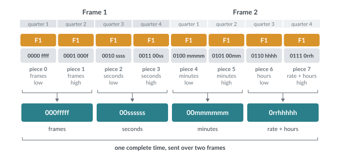
While the system is running, the time above is sent a nibble at a time in quarter-frame messages, four per frame, or up to 120 per second at 30 fps. Each is just two bytes: the status byte F1 and a data byte holding a 3-bit piece number (0–7) and one nibble of the time. It takes two full frames to complete all eight nibbles before the next complete time begins. Because the last piece arrives two frames after the first, a receiver adds two frames to the time it has assembled.
Eight quarter-frame messages over two frames. Each data byte holds a 0, a 3-bit piece number and one nibble of the time.
However, when the system locates, fast-forwards or rewinds to a new position, a longer full message is sent, which carries the whole time at once and identifies itself as time code. In hex, this looks like:
F0 7F 7F 01 01 rh mm ss ff F7
[F0 7F]=Universal Real Time SysEx header, 7F=device ID, here all devices (so everyone pays attention to it; it can also be one device's ID), [01 01]=this is the time code full message, then rate/hour, minutes, seconds, frames, F7=End of SysEx message (EOX).
Frame rates are a tricky subject—it is important for anyone synchronizing to video that they know what frame rate and format the video was encoded in and that they set their MIDI sequencer frame rate to match. Fortunately, the storage capacity of current computers allows composers to import video files directly into their DAW sequencers to compose with, negating the need for much, but not all, of the original purpose of MIDI Time Code.
Why "Drop-Frame"?
Color NTSC video, the standard in North America and Japan, runs at 29.97 frames per second rather than 30. Time code that counts 30 frames a second therefore falls behind the clock on the wall by about 3.6 seconds an hour. Drop-frame time code makes up the difference by skipping two frame numbers, 00 and 01, at the start of every minute except every tenth one. No pictures are dropped; only the labels jump.
MIDI Sample Dump Standard (SDS)
I include this section only for completeness. Transferring samples via MIDI cable way back when was a long and tedious process, and fortunately these days, most samplers are either virtual or hook up to a hard drive where large sample sets can be loaded in seconds, not hours. This class of code grew out of a need to move samples (audio files stored on an instrument for playback) from an instrument to the computer, edit them, perhaps use a looping utility on the software to add loop points, and send them back to the instrument. The first computer program I can remember for doing this was Sound Designer from Digidesign. At the time it was developed, digital sampling instruments had very limited memory, perhaps 512 KB or less, so the samples used were typically very short. MIDI moves only about 3,000 bytes per second, and the original SDS handles only mono, so a one-minute stereo sample at CD quality (44.1 kHz, 16-bit), sent one channel at a time, would take about an hour and a half; a USB drive copies it in under a second.
MIDI Machine Control
MIDI Machine Control (MMC) is a set of universal SysEx messages for controlling the transport functions of connected tape decks and other recorders. MMC was used most successfully to synchronize a MIDI sequencing program with a digital audio recorder such as an ADAT or Tascam DA-88. MMC tells the deck to start, stop or pause, while MIDI Time Code keeps the tape synchronized with the sequencer. Its cousin, MIDI Show Control (MSC), similarly cues lighting and other theatrical devices, perhaps even fireworks and Christmas lights!
MMC and MTC have outlived the tape decks. Current DAWs such as Logic Pro and Cubase can still send MMC to start and locate an external recorder while following the MTC it sends back. Apple recommends MTC for syncing Logic to video or to another DAW such as Pro Tools.
