Chapter Two: Studio Gear
3. Microphones | Page 2
Microphone Placement, Controls and Characteristics
Decisions on microphone placement should be based on numerous issues:
- Direct source vs. reflections and room ambience
- Bass response vs. presence peak
- Stereo image best suited to the source and its ultimate use
- Dynamic range of the source
- Single-mic phase issues from reflected sound
- Time and phase issues in multiple mic'ing setups
Some of the terms, concepts and options below will help in making those choices.
Inverse Square Law: The inverse square law means that at half the distance between source and mic, a microphone receives four times the sound intensity—this is in a soundfield with no reflective surfaces. Consider this the mother of all mic-placement guidance. Therefore, a great deal of time should be spent adjusting the distance of a microphone to the source sound and testing it via playback, then readjusting if necessary. The difference between 1.5 feet and 3 feet (only 18") will drop your signal strength by 6 dB, to one quarter of its intensity! Halving the distance gains 6 dB—four times the intensity.
Sound from a point source in a free field; distances measured from the source.
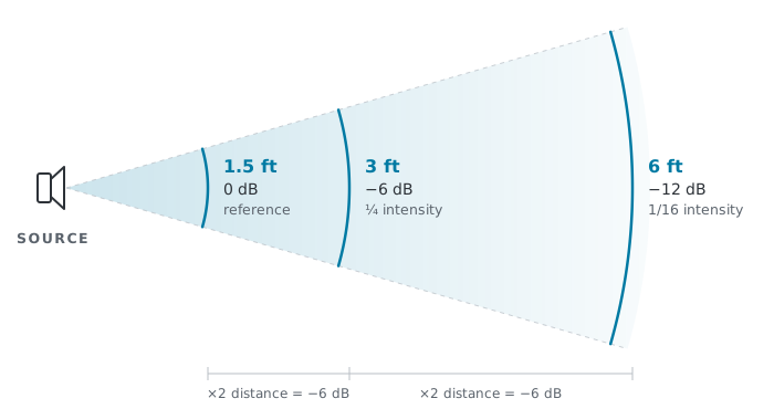
Each doubling of distance costs 6 dB and quarters the intensity, so 6 ft sits 12 dB below the 1.5 ft reference—one sixteenth the intensity.
Proximity Effect: The proximity effect exaggerates the low-frequency content of an acoustic source when a pressure-gradient microphone is placed near the source (within about two feet). The more directional the microphone, the greater the proximity effect will be. The bass boost (up to 16 dB) is caused by the amplitude difference between the front and back of the diaphragm becoming large relative to the phase difference. Also, the closer the mic to the source, the greater the exaggeration will be. The frequency at which this buildup begins—its corner frequency—rises as the mic moves closer, from roughly 45 Hz at two feet to over 1 kHz at an inch. You have undoubtedly heard this effect with 'boomy' radio personality voices. Pressure microphones, such as omnidirectional ones, exhibit essentially no proximity effect, since the effect depends on a rear port for the front and back of the diaphragm to differ.
An ideal cardioid in a free field; real microphones show less boost than this, since most build in some low-frequency rolloff.
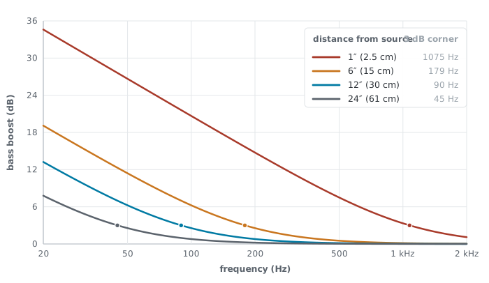
Each curve rises at 6 dB per octave below its corner frequency, marked by the dot where the boost reaches 3 dB. The closer the mic, the further right that dot sits, so bass buildup starts earlier and extends further up the spectrum.
Bass (low-frequency) rolloff is a control on a microphone that attenuates (lessens) low frequencies, including bass buildup caused by the proximity effect or floor vibrations transmitted through the mic stand (called rumble). The 'rolloff' means it is a slope, not a sudden drop at the rolloff frequency, as pictured here for the AKG C414 mic. The switch has a 0 Hz (or 'off') position and a selection of cut-off frequencies (e.g., 40/80/160 Hz). If you desire a full-range recording, do check to make sure this is in the '0 Hz' position.
Attenuator: The attenuation control reduces the strength of the signal coming from the microphone transducer by 10–20 dB (0 dB means no attenuation) to prevent distortion. In condenser mics this is normally an electrical divider ahead of the internal preamp, though a few designs use a mechanical baffle instead. The attenuation can help prevent overloading the internal preamp circuitry of a mic when subjecting the mic to very high acoustic levels. It cannot prevent the mechanical overload of the mic's diaphragm, but usually distortion is first caused by the preamp. Do not use this control as a quick substitute for adjusting the mic trims and fader levels on the mixing console. Normally, start with 0 dB attenuation, because recording low-volume sources with attenuation degrades the mic's signal-to-noise ratio.
Feedback is a loud ringing, screaming, often-undesirable sound created by an acoustic positive-gain loop between a live microphone and loudspeakers. Solution: turn the speakers off and monitor on headphones whenever recording in the same room. For sound reinforcement (i.e., amplifying sound potentially in the microphone's field), moving mics behind the speakers whenever possible is a start. Using mic patterns like cardioid and hypercardioid that are more directional with little or no rear lobes is also helpful, and/or making certain the rear lobes are pointed away from any potential feedback source. A graphic equalizer can be used to locate and attenuate the feedback frequencies, but only so long as the microphone is not moved afterward, since moving it changes those frequencies. The process of locating the feedback frequencies and attenuating them is called ringing out. This is usually not without impact on the timbre of the source you are amplifying. An objective measurement of how much a mic can be amplified before it feeds back is called gain before feedback, or GBF.
Colored Response: Microphones that do not linearly reproduce the frequency content of the source signal are considered colored. This is not always a bad thing. The ubiquitous Shure SM58, which is intended as a popular music vocal mic, has a presence peak that accentuates frequencies in the 2–7 kHz range. Virtually all microphones have non-linear characteristics that often vary with the polar pattern selected. You can compare the response plots for the various AKG C414 patterns.
Hole-in-the-Middle Effect, generally undesirable, describes a stereo recording in which the center of the ensemble sounds weak or vacant while the outer players sound fine. It arises two different ways. With coincident mics, angling the pair too widely leaves a center source off-axis of both microphones, so the middle of the ensemble is simply picked up at a lower level than the flanks. With a spaced pair—with two mics on separate stands—the cause is time rather than level. Sound from anywhere but dead center reaches one microphone measurably earlier than the other, and beyond roughly a millisecond of difference the ear stops splitting the difference and places the source at whichever speaker carries the earlier arrival. Both faults trade a solid center for exaggerated separation at the edges.
A cardioid spaced pair aimed straight ahead, 6 ft apart, facing an 8 ft ensemble from 12 ft.
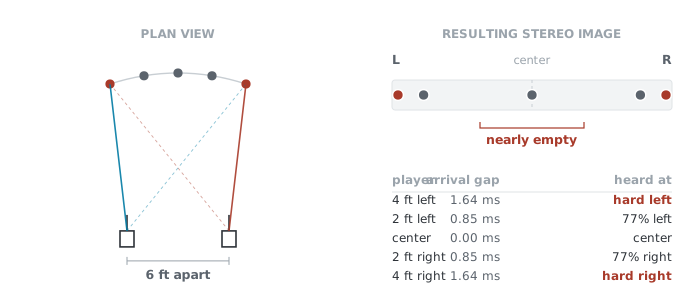
With an overly wide cardioid spaced pair, only a source at dead center reaches both mics at the same instant. Above about 1.1 ms of difference the ear stops splitting the difference and places the source at whichever speaker carries the earlier arrival, so the players pile up at the edges and the middle empties out. A legitimate spaced pair adds a center mic to fill this in.
Spot mics, also called accent mics, are close mics used in multitrack recordings or sound reinforcement situations to allow engineers to feature a particular instrument or instrument group. For recordings, several of the problems that crop up with spot mics are time/phase differences from the house mics (these can be easily corrected with digital editing), differences in ambience (artificial reverb can help), and bleed from other sources that one didn't want to highlight (acoustic baffles can help). There is also the problem of mechanical transmission of sound from foot tapping or stage vibration, so shock mounts are helpful. Even correcting for these difficulties, this author has experienced 'harshness' and other disagreeable issues when using spot mics for anything but limited, targeted use.
Outriggers, usually hung off to the sides, flanking the center array of mics, are often used in multitrack recording to pick up signals from a wide ensemble such as an orchestra or choir when using a narrow center array such as a Decca Tree.
Ambience refers to the amount of indirect signal recorded along with the source, often a mixture of room reverberation and possibly other unwanted sources, such as the HVAC vents. While there is no hard-and-fast rule for the 'perfect' spot to place your mics, knowledge of the inverse square law and of the microphone patterns, plus a lot of experimentation before the final take, will serve you well. An overly ambient, weak-sourced recording is very difficult to undo. Reverb, for example, can be added artificially but not taken away when recorded from the actual environment. On the other hand, mic'ing a source too closely may pick up unwanted artifacts from the source, such as bow friction, heavy breathing, or clicking keys. In the past, the European aesthetic was in part "record the hall, not the ensemble." That is an aesthetic more suited to acoustically outstanding halls. The 2:1 rule of ambience states that a hypercardioid microphone can be placed twice as far from a source as an omni and still capture the same balance of direct sound to room ambience. Other patterns have their own ratios, and a view of their patterns would make the reason clear.
Ambient mic: An additional mic or mics hung farther from the source so that the amount of room ambience can be adjusted in the mix.
Ambisonic mic'ing: Ambisonics is a spherical 360° surround format, developed in the 1970s, that specifies all dimensional axes, including those above and below the listener (left, right, up, down, front, back) and treats them all equally—a property called isotropic. A system that reproduces the full sphere, height included, is described as periphonic. Because the recording describes the sound field itself rather than individual speaker channels, a single recording can be decoded for many different speaker arrangements. Either separate mics, or dedicated ambisonic mics (such as a first-order tetrahedral mic) are used with precise angles. Higher-order ambisonics gives greater spatial resolution to the source material. The ambisonic signal must be encoded when recorded and decoded when played back, since it is not stored as channels but in what is called B-format: a single pressure signal, W, carrying overall level, plus three directional signals—X for front and back, Y for left and right, Z for up and down—shown below.
The four signals of B-format (the native recording format of ambisonics)—not four microphones, but one pressure signal and three directional ones, derived together.
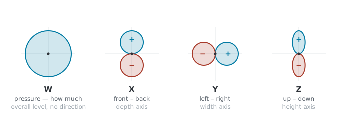
Overall pressure is in W, which has no directional information; the plus and minus lobes of X, Y, and Z carry opposite polarity. A decoder combines all four to rebuild whatever speaker feed is needed, which is why one ambisonic recording can serve many different playback arrangements.
Acoustic Baffle: A technique for achieving greater stereo separation with less cross-talk between channels by placing a sound-absorbent physical barrier between close mics. The baffled pair traces back to Alan Blumlein’s 1931 binaural patent, while Harvey Fletcher’s Bell Labs team was working with unbaffled spaced AB arrays in the same decade. A very cool modern example of baffling is the Jecklin disc technique, whereby a soft circular disc is placed between two omni microphones, each 3" away from the disc and angled out by 20°. Those are Jecklin's original figures; he later found the spacing too narrow and revised the design to a 35 cm disc with the mics 36 cm apart and aimed straight ahead, which is what most current references describe.
Microphone Impedance: Professional-level mics, preamps and boards are built to a common convention—low-impedance outputs feeding much higher-impedance inputs—so a composer using that class of gear can generally assume the pieces will work together. Impedance is a measurement of the total opposition an output or input presents to an alternating signal, measured in ohms (Ω). The greater the number of ohms, the higher the impedance. For microphone data sheets, the specs will usually give at least the output impedance, and for preamps or board inputs, the input impedance. Professional microphones will normally have output impedances in the 50–250 Ω range, considered low, and above 20,000 Ω (perhaps a $5 karaoke mic) is considered high (high-impedance mics can lead to hums and electrical interference in longer mic cable runs). On the other end, preamps, which form a circuit with an attached microphone, whether separate or part of a board input channel, should have input load impedances of at least 5 to 10 times the mic output impedance, so normally greater than 1,000–2,000 Ω. An example: the AKG C414 XLS mic has an output impedance of 200 Ω, and the mic preamp input load impedance of a Yamaha 01v96 board is rated at up to 3,000 Ω, so that would be a good match.
