Chapter Two: Studio Gear
3. Microphones | Page 4
Microphone Patterns (single microphone)
Depending on their design and construction, microphones respond to sound coming from different directions with varying degrees of sensitivity. A plot or graph of this response is called a polar pattern (sometimes polar response curve). Two-dimensional polar patterns are slices through the central axis of a three-dimensional pickup pattern, which you can imagine in 3D by rotating the plot 360° around its central 0°–180° axis, or viewing this 3D Beyerdynamic plot (it looks more like a futuristic tech graphic from a Spider-Man movie).
The most frequently used single microphone patterns are (select to scroll to plot):
Cardioid | Hypercardioid | Supercardioid | Figure-8 | Omnidirectional
One pattern is not 'better' than another—it depends on how you choose to use a particular mic, which sound characteristics you are most after (more or less room ambience, feedback avoidance for live sound, etc.), and what the nature of your sound source is. It is important to note that polar patterns are frequency-dependent. Typically, low-frequency response will be almost omnidirectional; the polar pattern, even for omnidirectional mics, will become more directional as frequency rises. For our purposes, generalized plots of the patterns are used here, but before putting a lot of money down on a good microphone, it may be prudent to view the pattern response for various frequency bands for the mics you are considering and make sure the mic is best suited for the uses you have in mind. For example, this AKG C414 XLS hypercardioid plot (hover to see, click for full C414 data sheet) indicates a much wider pickup pattern for 2 kHz–8 kHz than for 16 kHz and above. The degree of pattern difference in these frequency bands as sound moves around a mic off the front is called off-axis coloration. Typically, as is the case with this C414 plot, many mics lose their high-frequency sensitivity off-axis compared to their low end.
Polar Pattern Plots: The direction of the arriving sound relative to the axis of the mic is called the angle of incidence. Looking at a mic's polar pattern will tell you how directional it is, how well it will reject sound from certain directions, etc. The plots aid in assessing the pattern's acceptance angle, which can be defined as the total angle within which sensitivity stays within 3 dB of the on-axis response. As you examine the plots below, note for example that the standard cardioid has an acceptance angle of about 131° while the supercardioid narrows to about 115°, indicating the degree of directionality of the mic choice.
Some microphone patterns are partially bidirectional because they have more than one lobe or area of response bounded by a null or near-null where virtually all sound is rejected. Sound entering the rear lobe is usually in reverse phase to its 'on-axis' counterpart.
How to Read: The plots on this page indicate the amount of sensitivity relative to angle of incidence, with 0° directly on-axis at the top of each plot and the radial lines falling at 30° intervals. The outermost circle represents the on-axis maximum, and each circle inside it marks another 5 dB of attenuation, down to -25 dB. Looking at the cardioid graph immediately below, it indicates that for sound arriving at 0°, the relative sensitivity is at the maximum, with 0 dB attenuation, but for sound arriving 120° off-axis, the sensitivity drops by approximately 12 dB, as the plot crosses between the -10 and -15 dB circles at the 120° mark. The shaded wedge marks the acceptance angle described above: the two dots sitting on the curve are the -3 dB points, and the wedge spans the angle between them. The narrower the wedge, the more selective the mic. An omnidirectional microphone has no such boundary, which is why its plot carries no wedge at all.
For the math-brave: every pattern on this page is derived from the same equation with one number changed. If θ is the angle off-axis and a is a constant from 0 to 1, sensitivity is p = a + (1 − a) cos θ. Let a = 1 and the cosine term vanishes, leaving an omni; around 0.7 gives a wide cardioid or subcardioid, 0.5 a cardioid, (√3 − 1) / 2 ≈ 0.366 a supercardioid, 0.25 a hypercardioid, and 0 a figure-8. On-axis, θ = 0 and p = 1 no matter what a is, so every plot is measured against its own front. The nulls fall wherever p = 0, which is why patterns with a above 0.5 have none at all. The edges of the shaded wedge fall wherever p = 0.707 (1/√2)—the amplitude that corresponds to half the power, or −3 dB. Where p goes negative, you have a rear lobe, and the minus sign is the phase inversion mentioned above.
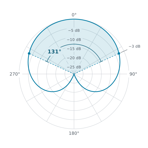
Cardioid mics are characterized by strong sensitivity to audio from the front ('on-axis'), good sensitivity on the sides (at 90°, about 6 dB less than the front), and good rejection of sound from the rear. The cardioid pattern is roughly heart-shaped (hence the name). The ability to reject sound from the rear makes cardioid patterns very useful in multi-mic'ing situations, and where it is not desirable to capture a large amount of room ambience from behind. Popular in both studio and live use (where rear rejection cuts down on feedback and ambient noise), cardioid mics are used for a very high percentage of microphone applications. Keep in mind that, like all pressure-gradient mics, cardioid mics will exhibit a pronounced proximity effect and be more susceptible to breath blasts such as vocal plosives.
Cardioid mics work on the pressure-gradient principle, whereby sound entering through side vents, ports or a rear screen travels a hollow labyrinth of channels to reach the rear of the diaphragm after a built-in delay. The delay is chosen so that sound arriving from behind reaches both faces of the diaphragm at the same instant, where the equal and opposing pressures cancel and produce the rear null.
Cardioid mics are very commonly used in stereo pair mic'ing, such as X-Y coincident and ORTF or other near-coincident techniques, and as the forward-facing mid microphone in Mid-Side (M-S) recording.
There is a variant of the cardioid pattern known as wide cardioid, also sometimes called subcardioid, which acts as a compromise between an omni and a cardioid. It has a very broad front area (hence "wide"), no null points, and it still picks up sound from the rear, though at a reduced level. Its acceptance angle measures roughly 177°, against the standard cardioid's 131°. The newer AKG C414 models added this pattern.
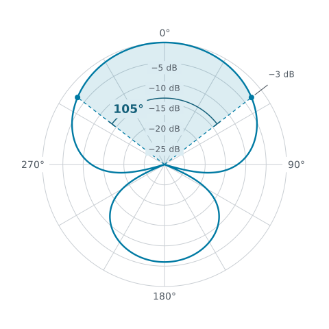
Hypercardioid patterns are similar to cardioid patterns in that the primary sensitivity is in the front of the microphone. They differ, however, in that the points of least sensitivity (again, called nulls) are at the 110° and 250° positions, as opposed to directly behind the microphone in a cardioid pattern. Hypercardioid microphones are thus considered even more directional than cardioid and supercardioid microphones, with an acceptance angle of only about 105° at the 3 dB limits, compared to the cardioid's 131°.
Hypercardioid microphones are frequently used in situations where maximum isolation from off-axis sound sources is desired, including for film work. The rear lobe receives a lesser amount of sound from behind than the front, and it is in inverted phase relative to the front. This pattern is a good choice if you wish to include some room ambience from the back of the hall or other environment. A hypercardioid pattern can be considered the halfway point between a cardioid and a figure-8 in terms of its bidirectionality. For live sound, it's a good idea not to point the rear lobe directly at something like a stage monitor without feedback control. As with the cardioid, the hypercardioid mic works on the pressure-gradient principle and is likewise prone to proximity effect and to breath blasts such as plosives.
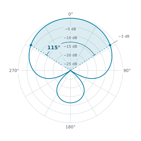
Supercardioid patterns are very similar to, and often confused with, the hypercardioid pattern. They typically have null points around 125° and 235°. The supercardioid pattern is slightly less directional than the hypercardioid pattern, and the rear lobe of sensitivity is also much smaller than the hypercardioid's. The supercardioid also works on the pressure-gradient principle, and is therefore also prone to proximity effect and to breath blasts such as plosives.
Highly directional shotgun mics usually have a hyper- or supercardioid capsule placed deep inside a long tube (called an interference tube) that cancels most off-axis sound by phase interference, hence the name, with a small amount allowed in from the rear. These are very popular for video applications, mounted on the camera, since they acquire sound primarily in the direction the camera is pointed. These lobar shotguns may also show small side lobes arising from the slots along the tube.
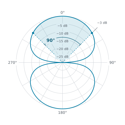
In the figure-8 or bidirectional microphone polar pattern, the mic is (nearly) equally sensitive to sounds picked up from front and back, but not sensitive to sounds on the sides, with nulls at 90° and 270°. This produces a pattern that looks like a figure-8 on paper, where the microphone is at the point of crossover on the '8.' Many of these microphones form the pattern with a second cardioid diaphragm on the rear face of the backplate, combined out of phase with the front. They work on the pressure-gradient principle mentioned above. A Blumlein pair, shown on the next page, uses a pair of figure-8 microphones at right angles to each other.
Because they are pressure-gradient mics with no rear attenuation, figure-8 microphones are the most susceptible to overloading from breath blasts such as plosives and also demonstrate the most proximity effect. Figure-8 mics are almost always side-address mics, like the AKG C414 mentioned above. Most ribbon mics are inherently figure-8, since the ribbon is exposed equally to the front and back of the mic.
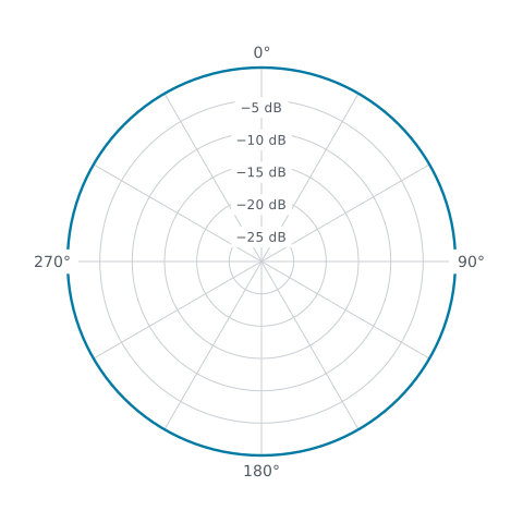
An omnidirectional mic (often called an omni) has a theoretically identical sensitivity in all directions, though often physical structures on the mic prevent a perfect circle of response. In addition, as mentioned earlier, omnis may become more directional at higher frequencies. An omnidirectional microphone will not exhibit proximity effect. Omni pairs have been used to create unusual spatial effects in concert halls by hanging one a significant distance behind the other, resulting in intentional time-of-arrival and phase differences controllable by the mix at the board. This arrangement allows engineers to control the amount of drier direct signal vs. ambient reverberant signal.
The British recording company Decca developed a favored array for recording orchestral music using two spaced omnis, with the center bolstered by a third omni set a meter or so forward of the pair. This array, with many variations, is known as a Decca tree, and variations include hanging a second pair of "outrigger" omnis wider still, near the outer edges of the ensemble, for example.
Unlike the other patterns listed above, a true omni mic works on the pressure, not pressure-gradient, principle in that only the front of the diaphragm is exposed to the sound field; the rear is sealed in a closed cavity. Some mics with back-to-back capsules, like the AKG C414, derive their omni setting by mixing the rear capsule in phase with the front. The result falls short of a true omni, and partial nulls may remain at the sides.
