Chapter Two: Studio Gear
4. Mixing Consoles | Page 5
The Master Section
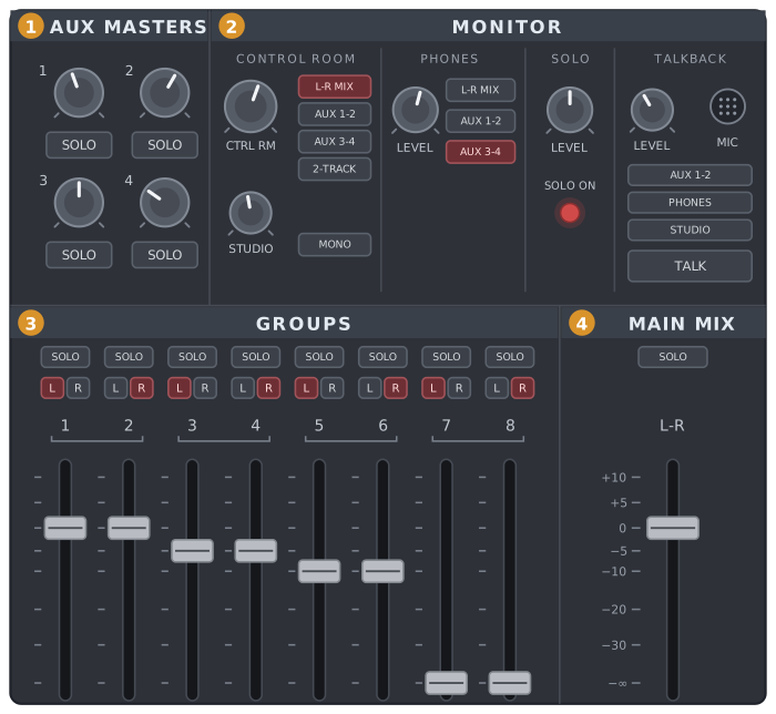
The whole master section—blocks 1 and 2 are on this page
1Effect/Aux Send Master Section
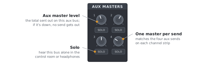
The aux send master section controls the total amount of signal sent out on each of the four aux buses: the sum of every channel’s aux send to that bus. You can monitor one or more aux buses by pressing their solo buttons. Novice users often forget to turn up the aux send masters and consequently no signal is sent to the aux device.
This is a good place to mention the gain staging of an effects loop—that is, all the controls where the aux send signal may be boosted or cut. The signal passes first through the aux send pots on the input channel strips, then through the aux send master and into the effects box. The effects box likely has its own input level pot, and these are often very sensitive: send enough signal to stay well above the noise, but not so much that the effect’s input distorts. On the way back, the effect’s output level and the effects return complete the loop.

In your DAW
Using Aux Tracks for Effects Plug-ins in Your DAW Mix
Chances are you are not using external effects boxes anymore, but DAW plug-ins instead. Here is your chance to up your mixing game by sharing your common plug-ins through aux tracks. For example, most people starting out add a separate reverb plug-in for each input channel, even though the reverb may have the same setting for all. This makes it tedious to set the overall reverb level for the piece. Instead, borrow the console’s effects loop. Each track’s send plays the part of a channel aux send, the bus it feeds is the aux bus, and an aux track holding a single reverb plug-in is the effects return. In Digital Performer, choose Project→Add Track→Aux Track, add your reverb plug-in to the new aux track, and set its input to the bus you plan to use for reverb. Then set the sends on your tracks to that same bus. Use each track’s send to feed as much or as little of it to the reverb as you like. The aux track’s fader is now your reverb return: one fader sets the overall level of reverb in the piece, and changing the reverb itself, or any other shared effect, means adjusting one plug-in’s settings instead of many.
For concerts, the same setup is extremely handy for an on-stage monitor mix. Leave out the plug-in and set the aux track’s output to the interface output that feeds the stage monitors: its fader now acts as a true send master, so the engineer can adjust the whole monitor level with a single fader rather than each input channel’s send.
2The Monitor Section
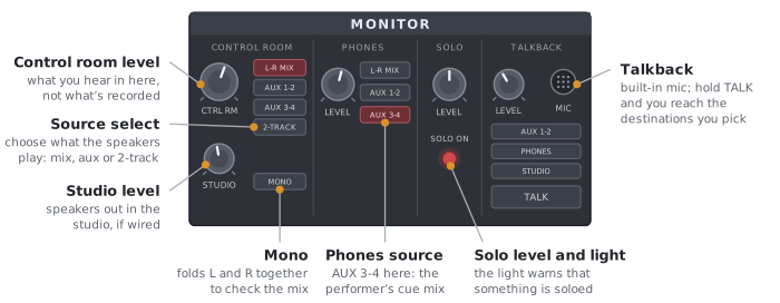
The monitor section may control what signals and levels are sent to the studio speakers (usually limited to two channels), the control room speakers, the talkback circuit (for communicating with artists or thieves in the studio, or conductors on stage), and headphones. This depends on how the board has been configured by the studio overseers, as many studios, particularly multi-track studios, have speakers connected directly from the main output faders and bypass this section. Use the source buttons to select the source that you are monitoring. If your speakers are wired from the studio or control room outputs, press L-R MIX as the source to hear the main stereo mix. This is one of the first things you should check if you get no sound out of the board. This section also holds the solo bus’s master level and its warning light.
If you are recording a performer and wish to send only certain channels at various levels into their headphones, you choose their source bus here. For example, you might select AUX 3-4 as the phones source, then turn up aux sends 3 and 4 on just the channels the performer wants to hear. The two sends work as a left-right pair, so their balance places each channel in the headphones.
If your studio uses the control room pot to feed the control room speakers, it is important to realize that the level of signal emanating from the control room speakers is not necessarily the level of signal being sent out of the board and recorded, or sent into the concert hall if you are doing playback from a control room. That is controlled by the output section (see the next page). Watch the output meters for levels actually being sent to recording devices.
